flange-hardwareinstallation-kits
81000 Series Aluminum Gate Valves
81000 Series Aluminum Gate Valves
21700 Series Stainless Steel 3-Position Gate Valves
21700 Series Stainless Steel 3-Position Gate Valves
71000 Series Stainless Steel Harsh Process Gate Valves
71000 Series Stainless Steel Harsh Process Gate Valves
88200 / 28200 Series Rectangular / Slit Valve
88200 / 28200 Series Rectangular / Slit Valve
4000 Series Angle Valve
4000 Series Angle Valve
21200 Series Stainless Steel Million Cycle Gate Valves
21200 Series Stainless Steel Million Cycle Gate Valves
May 7, 2013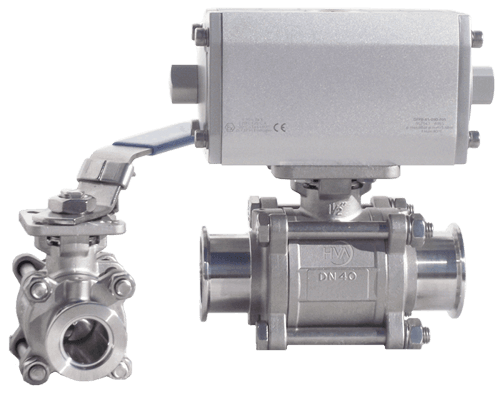
2000 Series Stainless Steel Ball Valves
2000 Series Stainless Steel Ball Valves
April 26, 2013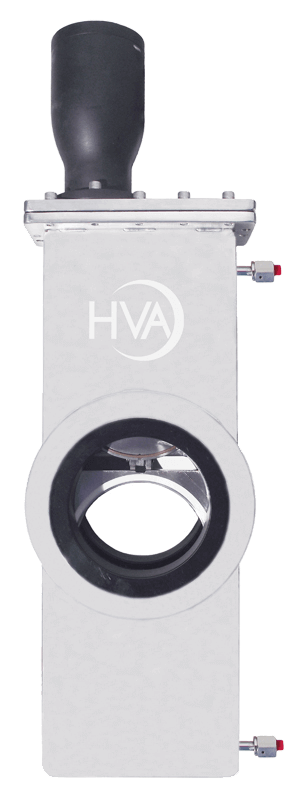
13000 Series Stainless Steel Laminar Flow Gate Valves
13000 Series Stainless Steel Laminar Flow Gate Valves
May 7, 2013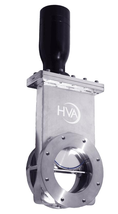
16000 Series Stainless Steel Shielded Gate Valves
16000 Series Stainless Steel Shielded Gate Valves
Valves
11000 Series Stainless Steel Gate Valves
Description
The KF, ISO-F, ISO-K, ASA and JIS flanged 11000 Series Standard Cycle Gate Valves are designed for high vacuum applications. These valves provide valving for cryopumps, turbo pumps, ion pumps and other applications requiring clean, low outgassing valves. Metal-sealed CF flanges provide compatibility with UHV systems when pressure ranges approximate 1 x 10⁻¹⁰ mbar and higher bakeout temperatures of 200°C are needed. These valves can also be configured for higher temperatures.
Standard Technical Specifications
Materials
Valve body and gate: 304 stainless steel
Welded bellows shaft seal: AM-350
Vacuum
Pressure Range:
- HV: 1×10⁻⁹ mbar
- UHV: 1×10⁻¹⁰ mbar
Helium leak rate: <2×10⁻⁹ mbar I/s
Differential pressure closed: 1 bar in either direction
Maximum Δ pressure before opening: <30 mbar
Mechanism
Manual: hand crank
Pneumatic air service: 80 psig
Solenoid :
- supplied voltage: 120V AC, 50/60 Hz
- optional voltages: 24, 200, 240 VAC 50/60 Hz or 12, 24V DC
Position indicator, max: 115 VAC or 28 VDC, 20 mA
Bonnet / gate seals
HV: Viton® elastomer
UHV: Copper / Viton® elastomer
Bakeout Temperature
without solenoid
Elastomer sealed bonnet: 150°C
Metal sealed bonnet:
- Value open: 200°C
- Value closed: 150°C
Actuator:
- Manual: 60°C
- Pneumatic: 60°C
Mounting Position
Any
Cycles Until Service
100,000 Cycles dependent on process
To obtain 2D drawings (PDF),3D drawings (STP), and to request a quote follow the links below
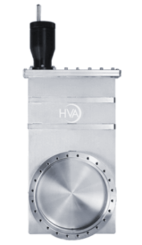
81000 Series Aluminum Gate Valves
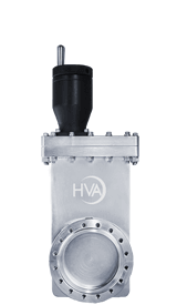
Description
The 81000 Series Aluminum Gate Valves are designed for high vacuum applications specifically when pressure ranges approximate 1 x 10⁻⁷ mbar and bakeout temperatures do not exceed 150°C. These valves are designed for system integrators, designers and OEM’s within the Semiconductor, Solar, LED/FPD, Coating and BioPharm industries due to their robust design and low cost. They feature precision machined high strength aluminum bodies from solid 6061-T6 billet, dual quad ring long life shaft seals and high performance PEEK components.
Standard Technical Specifications
Materials
Valve body and gate: 6061-T6 aluminium
Shaft: [DN40-80 AL/[DN100-500]304SS]
Carriage: 6061-T6 Aluminium/PEEK
Bonnet/gate/shaft seals: Viton® elastomer
Bakeout Temperature
without solenoid
Valve Body and Gate: 120°C
Actuator: 80°C
Vacuum
Pressure Range
HV: 1x10⁻⁹ mbar
Helium leak rate: <2x10⁻⁹ mbar l/s
Differential pressure closed: 1 bar in either direction
Maximum Δ pressure before opening: ≤30 mbar
Mounting Position
Any
Vacuum
Pressure Range: 1x10⁻⁷ mbar
Helium leak rate: < 2x10⁻⁹ mbar l/s
Differential pressure: ≤ 1.6 bar in either direction
Differential pressure at opening: ≤30 mbar
Mechanism
Manual: hand crank
Pneumatic air service: 80 psig
Solenoid: 4.0 Watts
- supplied voltage: 120V AC, 50/60 Hz
- optional voltages: 24, 200, 240 VAC, 50/60 Hz or 12.24V DC
Position indicator, max: 115 VAC or 28 VDC, 20mA
Cycles Until Service
[DN40-160]: 400,000 cycles
[DN200-320]: 250000 cycles
Options
Use the table below to obtain 2D drawings (PDF) and 3D drawings (STP), or to request a quote.
If you need help finding a model number use the following link: 81000 Series Model Key Guide
Pneumatic with Elastomer Bonnet and Gate O-Ring (includes reed switch position indicators)
Pneumatic – Viton Seals without Solenoid and Position Indicator
| DN | Model Number | KF/ISO-F 3 (Bolted) | ISO-K 6 (Clamped) | CF-F* 0 or 4 (Conflat) | |||||||
|---|---|---|---|---|---|---|---|---|---|---|---|
| mm | inch | ||||||||||
| 40 | 1.50 | 81210-015_R | 2D | 3D | Quote | – | – | – | 2D | 3D | Quote |
| 50 | 2.00 | 81210-020_R | 2D | 3D | Quote | – | – | – | 2D | 3D | Quote |
| 63 | 2.50 | 81210-025_R | 2D | 3D | Quote | 2D | 3D | Quote | 2D | 3D | Quote |
| 80 | 3.00 | 81210-030_R | 2D | 3D | Quote | 2D | 3D | Quote | 2D | 3D | Quote |
| 100 | 4.00 | 81210-040_R | 2D | 3D | Quote | 2D | 3D | Quote | 2D | 3D | Quote |
| 160 | 6.00 | 81210-060_R | 2D | 3D | Quote | 2D | 3D | Quote | 2D | 3D | Quote |
| 200 | 8.00 | 81210-080_R | 2D | 3D | Quote | 2D | 3D | Quote | 2D | 3D | Quote |
| 250 | 10.00 | 81210-100_R | 2D | 3D | Quote | – | – | – | 2D | 3D | Quote |
| 320 | 12.00 | 81210-120_R | 2D | 3D | Quote | – | – | – | 2D | 3D | Quote |
Flange Types
- 0 = CF-F Port with UNF Thread (81210-0400)
- 3 = KF/ISO-F Bolted (81210-0403)
- 4 = CF-F Port with UNF Thread (81210-0404)
- 6 = ISO-K Clamped (81210-0406)
Manual with Elastomer Bonnet and Gate O-Rings (no position indicators)
| DN | Model Number | KF/ISO-F 3 (Bolted) | ISO-K 6 (Clamped) | CF-F* 0 or 4 (Conflat) | |||||||
|---|---|---|---|---|---|---|---|---|---|---|---|
| mm | inch | ||||||||||
| 40 | 1.50 | 81110-015_ | 2D | 3D | Quote | – | – | – | 2D | 3D | Quote |
| 50 | 2.00 | 81110-020_ | 2D | 3D | Quote | – | – | – | 2D | 3D | Quote |
| 63 | 2.50 | 81110-025_ | 2D | 3D | Quote | 2D | 3D | Quote | 2D | 3D | Quote |
| 80 | 3.00 | 81110-030_ | 2D | 3D | Quote | 2D | 3D | Quote | 2D | 3D | Quote |
| 100 | 4.00 | 81110-040_ | 2D | 3D | Quote | 2D | 3D | Quote | 2D | 3D | Quote |
| 160 | 6.00 | 81110-060_ | 2D | 3D | Quote | 2D | 3D | Quote | 2D | 3D | Quote |
| 200 | 8.00 | 81110-080_ | 2D | 3D | Quote | 2D | 3D | Quote | 2D | 3D | Quote |
Flange Types
- 0 = CF-F Port with UNF Thread (81110-0400)
- 3 = KF/ISO-F Bolted (81110-0403)
- 4 = CF-F Port with UNF Thread (81110-0404)
- 6 = ISO-K Clamped (81110-0406)
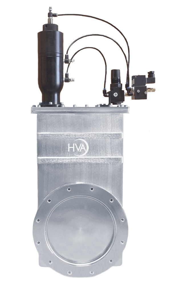
21700 Series Stainless Steel 3-Position Gate Valves
Description
The 3-Position Gate Valves are designed for use in etching, CVD and any other process that requires pressure control. When used in conjunction with upstream mass flow controllers, this series valve will contribute to an exceptional pressure control capability. These valves may also be utilized to smooth the transition from rough to high vacuum. The valves employ two pneumatic solenoids and an air pressure regulator to achieve the three positions of fully open, fully closed, and an adjustable third position. One solenoid controls the fully open and fully closed positions while a second solenoid controls the third position.
Standard Technical Specifications
Materials
Valve body and gate: 304 stainless steel
Welded bellows shaft seal: AM-350
Drive shaft and pin: Hardened stainless steel
Vacuum
Pressure Range: 1×10⁻⁹ mbar
Helium leak rate: <2×10⁻⁹ mbar l/s
Differential pressure closed: 1 bar in either direction
Maximum Δ pressure before opening: < 30 mbar
Mechanism
Pneumatic air service: 80 psig
Solenoid: 4.0 Watts
- supplied voltage: 120V AC, 50/60 Hz
- optional voltages: 24, 200, 240 VAC, 50/60 Hz
Position indicator, max
- Reed switch for open & closed: 115 VAC or 28 VDC, 20 mA
- Microswitch for third position: 115 VAC, 5 A
- optional voltages: 250 VA, 5 A or 28 VDC, 5 A resistive load 28 VDC, 3 A inductive load
Cycles
1,000,000 cycles
Cycles until service: dependent on process
Bonnet/gate seals
HV: Viton® elastomer
Helium leak rate: <2×10⁻⁹ mbar l/s
Differential pressure closed: 1 bar
Temperature
Body: 150°C
Actuator: 60°C
Mounting Position
Any
Use the table below to obtain 2D drawings (PDF) and 3D drawings (STP), or to request a quote.
If you need help finding a model number use the following link: 21700 Series Model Key Guide
3-Position (includes elastomer seals with 120V AC solenoid and position indicators)
| DN | Model Number | KF/ISO-F 3 (Bolted) | ISO-K 6 (Clamped) | CF-F* 0 or 4 (Conflat) | |||||||
|---|---|---|---|---|---|---|---|---|---|---|---|
| mm | inch | ||||||||||
| 100 | 4.00 | 21712-040_R | 2D | 3D | Quote | 2D | 3D | Quote | 2D | 3D | Quote |
| 160 | 6.00 | 21712-060_R | 2D | 3D | Quote | 2D | 3D | Quote | 2D | 3D | Quote |
| 200 | 8.00 | 21712-080_R | 2D | 3D | Quote | 2D | 3D | Quote | 2D | 3D | Quote |
| 250 | 10.00 | 21712-100_R | 2D | 3D | Quote | – | – | – | 2D | 3D | Quote |
| 320 | 12.00 | 21712-120_R | 2D | 3D | Quote | – | – | – | 2D | 3D | Quote |
Flange Types
- 0 = CF-F Port with UNF Thread (21712-0400R)
- 3 = KF/ISO-F Bolted (21712-0403R)
- 4 = CF-F Port with Metric Thread (21712-0404R)
- 6 = ISO-K Clamped (21712-0406R)
Options
- JIS, ASA and Custom flanges
- Alternate o-ring material
- Alternate solenoid voltages
- UHV copper bonnet version
- Roughing ports
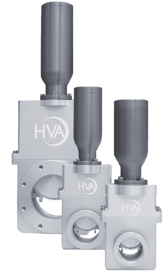
71000 Series Stainless Steel Harsh Process Gate Valves
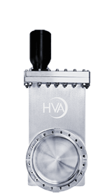
Description
The 71000 Series HPV (Harsh Process Valves) are designed for the harshest of vacuum environments. In typical harsh applications like MOCVD, ALD, PECVD the valves are subject to aggressive chemicals and high temperatures. The byproducts can affect the operation of the wheels/bearings, linkages and can cause the valve to seize so our HPV addresses this issue with no moving parts and a bellows that stays isolated from the process. The valves feature a robust dual containment design for increased safety, sealed bellows isolated from process for less maintenance, easy in-situ cleaning and o-ring replacement for reduced downtime and an optional integrated soft pump feature for lower particles.
Extreme Durability – For your most demanding process applications
Increased Safety – Robust dual containment design
Maintenance Free – Sealed bellows isolated from process
Reduced Downtime – Easy in-situ cleaning and o-ring replacement
Improved Pump Performance – Pump overload protection/isolation
Lower Particles – Intergrated soft pump feature
Standard Technical Specifications
Materials
Valve body and gate: 304 stainless steel
Welded bellows shaft seal: AM-350
Bonnet / gate seals: FKM or FKKM/FFPM elastometer
Temperature
Body: 150°C
Actuator: 100°C
Mounting Position
Any
Cycles
Cycles until service: > 250,000 cycles
dependent on process
Vacuum
Pressure Range: 1×10⁻⁹ mbar
Helium leak rate: < 1x10⁻⁹ mbar l/s
Differential pressure closed: tested up to 7 bar in any direction
Differential pressure at opening: 1 bar
Mechanism
Manual: hand crank
Pneumatic air service: 55-80 psi
Solenoid: 120V AC, 24V DC 50/60 Hz
Position indicator, max: 115VAC or 28 VDC, 20mA
Use the table below to obtain 2D drawings (PDF) and 3D drawings (STP), or to request a quote.
If you need help finding a model number use the following link: 71000 Series Model Key Guide
Pneumatic with Elastomer Bonnet and Gate O-Ring(includes reed switch position indicator)
| DN | Model Number | KF/ISO-F 3 (Bolted) | ISO-K 6 (Clamped) | CF-F* 0 or 4 (Conflat) | |||||||
|---|---|---|---|---|---|---|---|---|---|---|---|
| mm | inch | ||||||||||
| 50 | 2.00 | 71210-020_R | 2D | 3D | Quote | – | – | – | 2D | 3D | Quote |
| 63 | 2.50 | 71210-025_R | 2D | 3D | Quote | 2D | 3D | Quote | 2D | 3D | Quote |
| 80 | 3.00 | 71210-030_R | 2D | 3D | Quote | 2D | 3D | Quote | 2D | 3D | Quote |
| 100 | 4.00 | 71210-040_R | 2D | 3D | Quote | 2D | 3D | Quote | 2D | 3D | Quote |
| 160 | 6.00 | 71210-060_R | 2D | 3D | Quote | 2D | 3D | Quote | 2D | 3D | Quote |
Flange Types
- 0 = CF-F Port with UNF Thread (71210-0400R)
- 3 = KF/ISO-F Bolted (71210-0403R)
- 4 = CF-F Port with Metric thread (71210-0404R)
- 6 = ISO-K Clamped (71210-0406R)
Manual with Elastomer Bonnet and Gate O-Rings(includes visual position indicator)
| DN | Model Number | KF/ISO-F 3 (Bolted) | ISO-K 6 (Clamped) | CF-F* 0 or 4 (Conflat) | |||||||
|---|---|---|---|---|---|---|---|---|---|---|---|
| mm | inch | ||||||||||
| 50 | 2.00 | 71110-020_V | 2D | 3D | Quote | – | – | – | 2D | 3D | Quote |
| 63 | 2.50 | 71110-025_V | 2D | 3D | Quote | 2D | 3D | Quote | 2D | 3D | Quote |
| 80 | 3.00 | 71110-030_V | 2D | 3D | Quote | 2D | 3D | Quote | 2D | 3D | Quote |
| 100 | 4.00 | 71110-040_V | 2D | 3D | Quote | 2D | 3D | Quote | 2D | 3D | Quote |
| 160 | 6.00 | 71110-060_V | 2D | 3D | Quote | 2D | 3D | Quote | 2D | 3D | Quote |
Flange Types
- 0 = CF-F Port with UNF Thread (71210-0400R)
- 3 = KF/ISO-F Bolted (71210-0403R)
- 4 = CF-F Port with Metric thread (71210-0404R)
- 6 = ISO-K Clamped (71210-0406R)
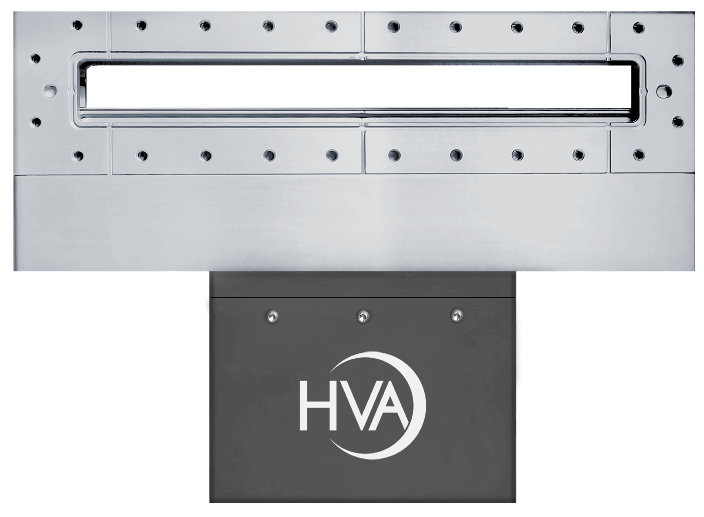
88200 / 28200 Series Rectangular / Slit Valve
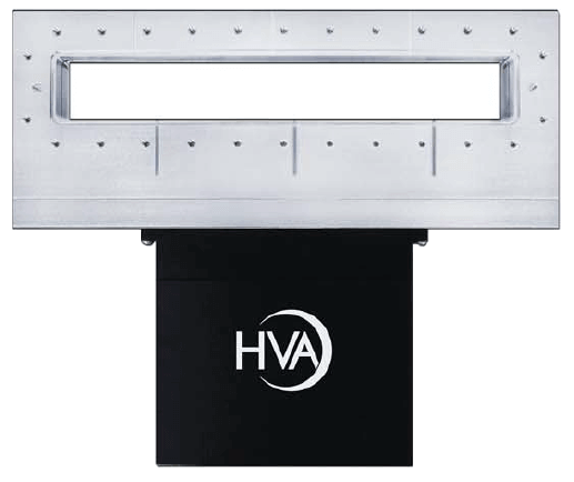
88200 Series Description
The 88200 Series Direct Drive Rectangular Valves offer one of the smallest interior surface areas in the vacuum valve industry. In the open position, the seal plate O-ring is completely out of sight preventing any particulate or media flow to accumulate on the sealing surface. In the closed position the one piece solid block design prevents any material buildup on the back side of the valve mechanism dramatically reducing service and maintenance requirements. This valve is engineered to meet the mechanical interface and vacuum containment requirements of the industry. To meet the specific needs of modular integrated processing systems, the valves are designed to isolate vacuum pressure on either side of the gate. A narrow profile design, including both actuator and controller, allows tight mounting between central, load-lock, handling and process chambers.
Standard Technical Specifications
Materials
Valve body and gate: 6061-T6 ALuminium
Welded bellows shaft seal: AM-350
Driveshaft and pins: Hardened stainless steel
Bonnet/gate seals: Viton® elastomer
Bakeout Temperature
without solenoid
Elastomer sealed bonnet: 150°C
Actuator: 60°C
Mounting Position
Any
Cycles Until Service
1,000,000 cycles
dependent on process
Vacuum
Pressure Range: 1×10⁻⁹ mbar
Helium leak rate: <2x10⁻⁹ mbar l/s
Differential pressure closed: 1 bar in either direction
Maximum ? pressure before opening: < 30 mbar
Mechanism
Pneumatic air service: 80 psig
Solenoid: 4.3 Watts
(latching-type, Valve to remain in same position in the event of power loss)
- supplied voltage: 120V AC, 50/60 Hz
- optional voltages: 24, 200, 240 VAC, 50/60 Hz or 12, 24V DC
Position indicator, max: 115 VAC or 28 VDC, 20 mA
Use the table below to obtain 2D drawings (PDF) and 3D drawings (STP), or to request a quote.
If you need help finding a model number use the following link: 88200 Series Model Key Guide
Pneumatic with Elastomer Bonnet and Gate O-Ring(includes reed switch position indicators)
| DN | Model Number | J (Bolted Body) | K (Clamped Body) | |||||
|---|---|---|---|---|---|---|---|---|
| mm | inch | |||||||
| 32 x 220 | 1.26 x 8.74 | 88212-0109RX_ | 2D | 3D | Quote | 2D | 3D | Quote |
| 32 x 332 | 1.26 x 13.07 | 88212-0113RX_ | 2D | 3D | Quote | 2D | 3D | Quote |
| 46 x 236 | 1.81 x 9.29 | 88212-0209RX_ | 2D | 3D | Quote | 2D | 3D | Quote |
| 50 x 336 | 1.97 x 13.23 | 88212-0213RX_ | 2D | 3D | Quote | 2D | 3D | Quote |
Options
- Custom sizes
- Alternate o-ring material
- Alternate solenoid voltages
- Microswitches for position indicators
- Roughing ports
- Low-particulate and rapid service versions
28200 Series Description
The 28200 Series Direct Drive Rectangular Valves offer one of the smallest interior surface areas in the vacuum valve industry. In the open position, the seal plate O-ring is completely out of sight preventing any particulate or media flow to accumulate on the sealing surface. In the closed position the one piece solid block design prevents any material buildup on the back side of the valve mechanism dramatically reducing service and maintenance requirements. This valve is engineered to meet the mechanical interface and vacuum containment requirements of the industry. To meet the specific needs of modular integrated processing systems, the valves are designed to isolate vacuum pressure on either side of the gate. A narrow profile design, including both actuator and controller, allows tight mounting between central, load-lock, handling and process chambers.
Standard Technical Specifications
Materials
Valve body and gate: 304 stainless steel
Welded bellows shaft seal: AM-350
Driveshaft and pins: Hardened stainless steel
Bonnet/gate seals: Viton® elastomer
Bakeout Temperature
without solenoid
Elastomer sealed bonnet: 150°C
Actuator: 60°C
Mounting Position
Any
Cycles Until Service
1,000,000 cycles
dependent on process
Vacuum
Pressure Range: 1×10⁻⁹ mbar
Helium leak rate: <2x10⁻⁹ mbar l/s
Differential pressure closed: 1 bar in either direction
Maximum ? pressure before opening: < 30 mbar
Mechanism
Pneumatic air service: 80 psig
Solenoid: 4.3 Watts
(latching-type, Valve to remain in same position in the event of power loss)
- supplied voltage: 120V AC, 50/60 Hz
- optional voltages: 24, 200, 240 VAC, 50/60 Hz or 12, 24V DC
Position indicator, max: 115 VAC or 28 VDC, 20 mA
Use the table below to obtain 2D drawings (PDF) and 3D drawings (STP), or to request a quote.
If you need help finding a model number use the following link: 28200 Series Model Key Guide
Pneumatic with Elastomer Bonnet and Gate O-Ring (includes reed switch position indicators)
| DN | Model Number | J (Bolted Body) | K (Clamped Body) | |||||
|---|---|---|---|---|---|---|---|---|
| mm | inch | |||||||
| 32 x 220 | 1.26 x 8.74 | 28212-0109RX_ | 2D | 3D | Quote | 2D | 3D | Quote |
| 32 x 332 | 1.26 x 13.07 | 28212-0113RX_ | 2D | 3D | Quote | 2D | 3D | Quote |
| 46 x 236 | 1.81 x 9.29 | 28212-0209RX_ | 2D | 3D | Quote | 2D | 3D | Quote |
| 50 x 336 | 1.97 x 13.23 | 28212-0213RX_ | 2D | 3D | Quote | 2D | 3D | Quote |
Options
- Custom sizes
- Alternate o-ring material
- Alternate solenoid voltages
- Microswitches for position indicators
- Roughing ports
- UHV version with copper bonnet
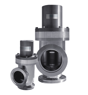
4000 Series Angle Valve
Description
The 4000 Series angle valves have been designed to offer maximum conductance with minimum size. These valves are ideally suited for systems where reliability and vacuum integrity are a major concern. The DN16-50 sizes have completed over 1.5 million cycles in reliability testing. They have replaced our previous 14000 angle valve series. Please contact HVA if you need support..
Standard Technical Specifications
Materials
Valve body and poppet: 304L stainless steel
Welded bellows seal: AM-350
Poppet / Bonnet Seals: Viton®
Temperature
Bake: 120°C
Operating: 90°C
Mounting Position
Any
Cycles Until Service
DN16-40: 1,500,000 cycles
DN50-250: 1,000,000 cycles
DN320-630: 100,000 cycles
Vacuum
Pressure Range: 1×10⁻⁹ mbar
Helium leak rate: <1×10⁻⁹ mbar l/s
Differential pressure closed: 1 bar
Mechanism
Manual: hand crank
Pneumatic air service: 60-95 psi
DN16-50 are air-to-open / spring-to-close
DN63-630 are air-to-open / air-to-close
Ordering Guides
If you need help finding a model number use the following the link: 4000 Series Model Key Guide
Pneumatic – Viton Seals without Solenoid and Position Indicator
| DN | Model Number KF/ISO-K | Model Number ISO-F | Model Number CF-F | |
|---|---|---|---|---|
| mm | inch | |||
| 16 | 0.625 | 04510-0073 | – | 04510-0070 |
| 25 | 1.0 | 04510-0103 | – | 04510-0100 |
| 40 | 1.5 | 04510-0153 | – | 04510-0150 |
| 50 | 2.0 | 04510-0203 | – | 04510-0200 |
| 63 | 2.5 | 04210-0256 | 04210-0253 | 04210-0250 |
| 80 | 3.0 | 04210-0306 | 04210-0303 | 04210-0300 |
| 100 | 4.0 | 04210-0406 | 04210-0403 | 04210-0400 |
| 160 | 6.0 | 04210-0606 | 04210-0603 | 04210-0600 |
| 200 | 8.0 | 04210-0806 | 04210-0803 | – |
| 250 | 10.0 | 04210-1006 | 04210-1003 | – |
| 320 | 12.0 | 04210-1206 | 04210-1203 | – |
| 400 | 16.0 | 04210-1606 | 04210-1603 | – |
| 500 | 20.0 | 04210-2006 | 04210-2003 | – |
| 630 | 25.0 | 04210-2506 | 04210-2503 | – |
Flange Types
- 0 = CF-F Port with Through Holes (04210-0400)
- 3 = KF/ISO-F Bolted (04210-0403)
- 6 = ISO-K Clamped (04210-0406)
Manual – Viton Seals without Position Indicator
| DN | Model Number KF | Model Number CF-F | |
|---|---|---|---|
| mm | inch | ||
| 16 | .625 | 04110-0073 | 04110-0070 |
| 25 | 1.0 | 04110-0103 | 04110-0100 |
| 40 | 1.5 | 04110-0153 | 04110-0150 |
| 50 | 2.0 | 04110-0203 | 04110-0200 |
| 63 | 2.5 | – | 04110-0250 |
Flange Types
- 0 = CF-F Port with Through Holes (04110-0100)
- 3 = KF (04110-0103)
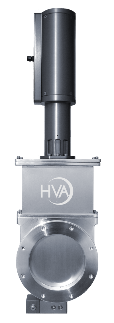
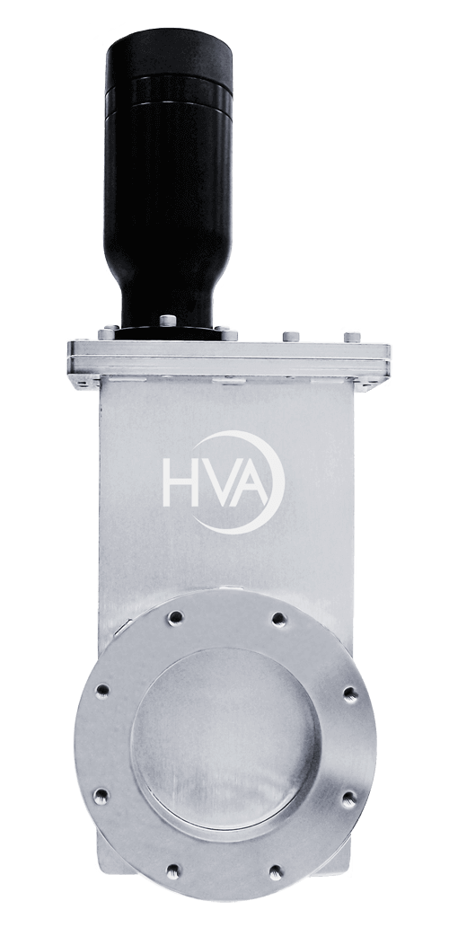
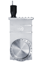
21200 Series Stainless Steel Million Cycle Gate Valves
Description
The 21200 Series Million Cycle Gate Valves are designed for high vacuum applications specifically when pressure ranges approximate 1 x 10⁻⁹ mbar and bakeout temperatures do not exceed 150°C. There are no mechanical locks inside vacuum, which is extremely beneficial for semiconductor and sensitive processes requiring vibration-free operation. All moving joints have hardened shafts, reducing particulate generation and providing smoother actuation. These valves provide valving for cryopumps, turbo pumps, ion pumps and other applications requiring clean, high cycle, low outgassing valves.
Standard Technical Specifications
Materials
Valve body and gate: 304 stainless steel
Welded bellows shaft seal: AM-350
Driveshaft and pins: Hardened stainless steel
Bonnet/gate seals: Viton® elastomer
Bakeout Temperature
without solenoid
Elastomer sealed bonnet: 150°C
Actuator: 60°C
Mounting Position
Any
Cycles Until Service
1,000,000 cycles
dependent on process
Vacuum
Pressure Range: 1×10⁻⁹ mbar
Helium leak rate: <2×10⁻⁹ mbar l/s
Differential pressure closed: 1 bar in either direction
Maximum Δ pressure before opening: ≤30 mbar
Mechanism
Manual: hand crank
Pneumatic air service: 80 psig
Solenoid: 4.0 Watts
- supplied voltage: 120V AC, 50/60 Hz
- optional voltages: 24, 200, 240 VAC, 50/60 Hz or 12, 24V DC
Position indicator, max: 115 VAC or 28 VDC, 20 mA
Use the table below to obtain 2D drawings (PDF) and 3D drawings (STP), or to request a quote.
If you need help finding a model number use the following link: 21200 Series Model Key Guide
Pneumatic with Elastomer Bonnet and Gate O-Rings (includes reed switch position indicators)
| DN | Model Number | KF/ISO-F 3 (Bolted) | ISO-K 6 (Clamped) | CF-F* 0 or 4 (Conflat) | |||||||
|---|---|---|---|---|---|---|---|---|---|---|---|
| mm | inch | ||||||||||
| 16 | 0.625 | 21212-006_ | 2D | 3D | Quote | – | – | – | 2D | 3D | Quote |
| 40 | 1.50 | 21212-015_R | 2D | 3D | Quote | – | – | – | 2D | 3D | Quote |
| 50 | 2.00 | 21212-020_R | 2D | 3D | Quote | – | – | – | 2D | 3D | Quote |
| 63 | 2.50 | 21212-025_R | 2D | 3D | Quote | 2D | 3D | Quote | 2D | 3D | Quote |
| 80 | 3.00 | 21212-030_R | 2D | 3D | Quote | 2D | 3D | Quote | 2D | 3D | Quote |
| 100 | 4.00 | 21212-040_R | 2D | 3D | Quote | 2D | 3D | Quote | 2D | 3D | Quote |
| 160 | 6.00 | 21212-060_R | 2D | 3D | Quote | 2D | 3D | Quote | 2D | 3D | Quote |
| 200 | 8.00 | 21212-080_R | 2D | 3D | Quote | 2D | 3D | Quote | 2D | 3D | Quote |
| 250 | 10.00 | 21212-100_R | 2D | 3D | Quote | – | – | – | 2D | 3D | Quote |
| 320 | 12.00 | 21212-120_R | 2D | 3D | Quote | – | – | – | 2D | 3D | Quote |
Flange Types
- 0 = CF-F Port with UNF Thread (21212-0400R)
- 3 = KF/ISO-F Bolted (21212-0403R)
- 4 = CF-F Port with Metric Thread (21212-0404R)
- 6 = ISO-K Clamped (21212-0406R)
Options
- Custom flanges
- UHV version with copper bonnet
- Alternate o-ring material
- Alternate solenoid voltages
- Microswitches for position indicators
- Roughing ports
- Motor operator
- High temperature components including o-rings, microswitches and actuator.
- Larger Sizes
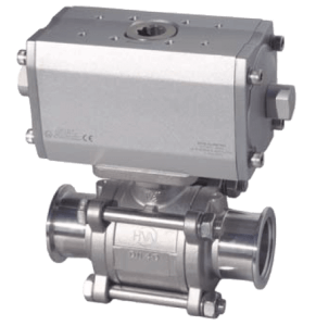
2000 Series Stainless Steel Ball Valves
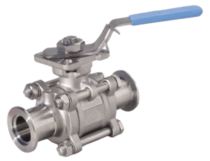
Description
HVA ball valves are the best choice for isolating gauges, foreline traps, petrochemical, abatement scrubbers, vacuum coating roughing lines, food processing lines and many more industrial applications.
Easy In-Situ Maintenance – Performed without disconnecting the valve from the sytem
Blow-Out Proof Stem – Assuring safety under high pressure conditions
Maximum Conductance – Offers full bore in the open position
Increased Service Intervals – Due to precision ball/seat design
Harsh and Corrosive Environments – Designed to withstand your harshest and most corrosive processes
High Quality 316L Stainless Steel – All wetted components
Fluoroelastomers – Guarantee vacuum tight sealing
PTFE Wiper – Removes any particulate from the ball
Standard Technical Specifications
Materials
Body/stem/ball/end caps: 316L stainless steel
Seat/gasket/stem packing: PTFE
Other components: 304L stainless steel
Temperature
Standard operating: -20°C to 150°C
Intermittent: Up to 200°C
Connections
KF, ISO, weld tube
Vacuum
Pressure Range: 1x10⁻⁸ mbar
Helium leak rate: < 1x10⁻⁸ mbar l/s
Differential pressure: 100 PSI
Mechanism
Manual: Easy turn handle
Pneumatic air service: 80 to 120 psi
(Fail safe option: air to open / spring to close)
To request a quote follow the links below
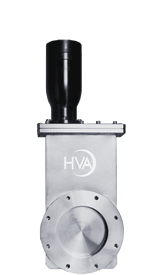
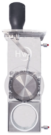
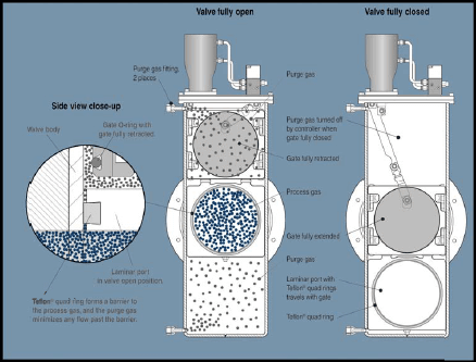
13000 Series Stainless Steel Laminar Flow Gate Valves
Description
The HVA 13000 Series Laminar Flow Gate Valve features a laminar flow port orifice that effectively seals the valve mechanism from the gas stream. For additional protection, purge ports are installed in both the upper and lower body areas to allow an insert gas flow to prevent intrusion of the process gas into these areas. Extensive semiconductor applications have proven these valves to be a valuable asset in process systems. Laminar flow valves may be used in etching, CVD and any other process that uses highly corrosive gases which may be damaging to other valves.
Standard Technical Specifications
Materials
Valve body and gate: 304 stainless steel
Welded bellows shaft seal: AM-350
Vacuum
Pressure Range
HV: 1x10⁻⁹ mbar
Helium leak rate: <2x10⁻⁹ mbar l/s
Differential pressure closed: 1 bar in either direction
Maximum Δ pressure before opening: ≤30 mbar
Mechanism
Manual: hand crank
Pneumatic air service: 80 psig
Solenoid: 4.0 Watts
- supplied voltage: 120V AC, 50/60 Hz
Position indicator, max: 115 VAC or 28 VDC, 20 mA
Cycles Until Service
100,000 cycles
dependent on process
Bonnet/gate seals
HV: Viton® elastomer
Bakeout Temperature
- Standard: 150°C
- Optional: 250°C
Actuator
- Pneumatic: 60°C
Mounting Position
Any
Purge Port Fittings
Standard: 1/4-inch female VCR
Optional: Swagelock, NW16 KF, Custom
Options
Custom flange sizes, Alternate voltage controls, Gauge ports, Microswitches, Million cycle option, QuickClamp Bonnet, Roughing ports, High-temp components
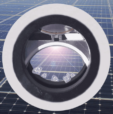
16000 Series Stainless Steel Shielded Gate Valves
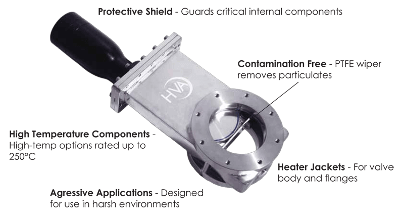
Description
The HVA 16000 Series Shielded Gate Valve features a travelling shield that moves with the gate to protect it from debris. These valves are used in extremely aggressive applications where reoccuring down time is not an option. The Shield greatly reduces particulate migration and prolongs the sealing integrity of the gate O-ring. The body material is 304 stainless steel, which can be changed to other high temperature, non corrosive materials for exceptionally aggressive applications. Alternative elastomer O-rings are also available.
Standard Technical Specifications
Materials
Valve body and gate: 304 stainless steel
Welded bellows shaft seal: AM-350
Vacuum
Pressure Range
- HV: 1×10⁻⁹ mbar
Helium leak rate: <2x10⁻⁹ mbar l/s
Differential pressure closed: 1 bar in either direction
Maximum Δ pressure before opening: ≤ 30 mbar
Mechanism
Manual: hand crank
Pneumatic air service: 80 psig
Solenoid: 4.0 Watts
- supplied voltage: 120V AC, 50/60 Hz
Position indicator, max: 115 VAC or 28 VDC, 20 mA
Bonnet/gate seals
HV: Viton® elastomer mbar
Bakeout Temperature
without solenoid
- Standard: 150°C
- Optional: 250°C
Actuator:
- Manual: 60°C
- Pneumatic: 60°C
Mounting Position
Any
Cycles Until Service
1,000,000 cycles
dependent on process
Options
Custom flanges, roughing ports, gauge ports, heater jackets, high temperature components including O-rings, microswitches and actuator